Description
This article explains how pods can communicate in a cluster of containers. It starts by explaining how the Linux kernel facilitates the configuration through networking namespaces and advances to how these namespaces are used by containers and K8s. I will not use the term “pod”( group of one or more containers ) as it is specific to Kubernetes jargon and I want to emphasize on the fact that the technical solutions employed in K8s can be used outside a K8s cluster. Keep in mind that everything explained here for containers applies to K8s pods. When trying to understand these concepts, I would recommend to approach it from 3 perspectives:
- communication between containers on the same host
- communication between containers on different hosts, same network
- communication between containers on different hosts, different networks
Networking
As the Docker website explains, there is no “container” component in the Linux kernel, but rather it’s a concept that abstracts several features that are used together to isolate and define the bounds in which a process or group of processes can execute. When you instruct a container runtime( containerd, cri-o) to instantiate a container, it will create a unique view of the system that is defined by the network interfaces, PIDs, IPCs, mounts and others.
Zooming on the network namespace paraphernalia, Linux abstracts 2 categories:
- a root namespace( default namespace, physical interfaces are connected here )
- scoped namespaces
# list network namespaces
sabin@sabin-pc:~$ sudo ip netns list

# add a network namespace
sabin@sabin-pc:~$ sudo ip netns add test

# add this point we can operate in the 'test' namespace and list interfaces
sabin@sabin-pc:~$ sudo ip netns exec test ip link list
1: lo: <LOOPBACK> mtu 65536 qdisc noop state DOWN mode DEFAULT group default qlen 1000
    link/loopback 00:00:00:00:00:00 brd 00:00:00:00:00:00

# we can see the loopback is 'DOWN' so we need to enable it
sabin@sabin-pc:~$ sudo ip netns exec test ip link set dev lo up

# we can now ping the loopback interface now
sabin@sabin-pc:~$ sudo ip netns exec test ping 127.0.0.1
PING 127.0.0.1 (127.0.0.1) 56(84) bytes of data.
64 bytes from 127.0.0.1: icmp_seq=1 ttl=64 time=0.031 ms
64 bytes from 127.0.0.1: icmp_seq=2 ttl=64 time=0.053 ms
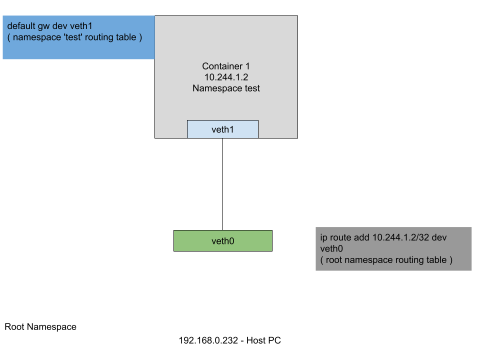
At this point we tested the network stack in the context of the ‘test’ namespace, but how can we access it from outside the namespace. To do this, a virtual ethernet devices pair need to be created. One end of the pair will be assigned to the namespace ‘test’ and the other will be left in the root namespace.
# create the veth pair
sabin@sabin-pc:~$ sudo ip link add veth0 type veth peer name veth1

# add one end to the 'test' namespace
sabin@sabin-pc:~$ sudo ip link set veth1 netns test

# assign and ip to it
sabin@sabin-pc:~$ sudo ip netns exec test ifconfig veth1 10.244.1.2/24 up

# check it( some output was deleted )
sabin@sabin-pc:~$ sudo ip netns exec test ip addr
25: veth1@if26: <NO-CARRIER,BROADCAST,MULTICAST,UP> mtu 1500 qdisc noqueue state LOWERLAYERDOWN group default qlen 1000
    link/ether d6:e3:c3:42:f9:6f brd ff:ff:ff:ff:ff:ff link-netnsid 0
    inet 10.244.1.2/24 brd 10.244.1.255 scope global veth1
       valid_lft forever preferred_lft forever
# ping it
sabin@sabin-pc:~$ sudo ip netns exec test ping 10.244.1.2
PING 10.244.1.2 (10.244.1.2) 56(84) bytes of data.
64 bytes from 10.244.1.2: icmp_seq=1 ttl=64 time=0.025 ms
How can we access it from the root namespace ? The way that the virtual ethernet pair works is that the traffic that goes in on one end is replicated on the other. So, we need to instruct the kernel to route the traffic to 10.244.1.2/32 through the veth0 interface and all the traffic that goes ouside the “container” through the veth1 interface.
# enable the veth0 device
sabin@sabin-pc:~$ sudo ifconfig veth0 up

# add route to 10.244.1.2/32 host from root namespace
sabin@sabin-pc:~$ sudo ip route add 10.244.1.2/32 dev veth0

# add default route through veth1 in the 'test' namespace
sabin@sabin-pc:~$ sudo ip netns exec  test ip route add default dev veth1

# print routing table in the 'test' namespace
sabin@sabin-pc:~$ sudo ip netns exec  test ip route
default dev veth1 scope link
10.244.1.0/24 dev veth1 proto kernel scope link src 10.244.1.2

# test
sabin@sabin-pc:~$ ping 10.244.1.2
PING 10.244.1.2 (10.244.1.2) 56(84) bytes of data.
64 bytes from 10.244.1.2: icmp_seq=1 ttl=64 time=0.029 ms

# side observations
# if you look at the arp traffic, you will see
sabin@sabin-pc:~$ sudo tcpdump -i any arp
13:02:58.517036 veth0 Out ARP, Request who-has 10.244.1.2 tell 192.168.0.232, length 28
13:03:03.706199 veth0 In  ARP, Request who-has 192.168.0.232 tell 10.244.1.2, length 28

# ping traffic
sabin@sabin-pc:~$ sudo tcpdump -i any icmp
13:04:59.476674 veth0 Out IP 192.168.0.232 > 10.244.1.2: ICMP echo request, id 4, seq 1, length 64

sabin@sabin-pc:~$ sudo ip netns exec test tcpdump -i any icmp
13:07:55.162113 veth1 In  IP 192.168.0.232 > 10.244.1.2: ICMP echo request, id 5, seq 40, length 64
13:07:55.162140 veth1 Out IP 10.244.1.2 > 192.168.0.232: ICMP echo reply, id 5, seq 40, length 64
At this point we understood how the communication is done with the “container”.
Communication between containers on the same host
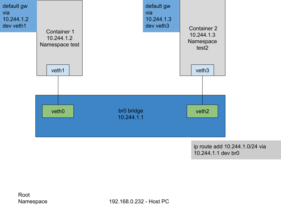
To replicate the communication between 2 “containers” on the same host we will duplicate the “container” namespace and connect them together through a network bridge.
# add 2 namespaces
sabin@sabin-pc:~$ sudo ip netns add test

sabin@sabin-pc:~$ sudo ip netns add test2

# add 2 virtual ethernet peers
sabin@sabin-pc:~$ sudo ip link add veth0 type veth peer name veth1

sabin@sabin-pc:~$ sudo ip link add veth2 type veth peer name veth3

# assign 2 ends in each namespace
sabin@sabin-pc:~$ sudo ip link set veth1 netns test

sabin@sabin-pc:~$ sudo ip link set veth3 netns test2

# set ip addresses
sabin@sabin-pc:~$ sudo ip netns exec test ifconfig veth1 10.244.1.2/24 up

sabin@sabin-pc:~$ sudo ip netns exec test2 ifconfig veth3 10.244.1.3/24 up

# enable ip virtual ethernet pair
sabin@sabin-pc:~$ sudo ifconfig veth0 up

sabin@sabin-pc:~$ sudo ifconfig veth2 up

# add a brige
sabin@sabin-pc:~$ sudo ip link add name br0 type bridge

# set bridge ip address
sabin@sabin-pc:~$ sudo ifconfig br0 10.244.1.1/24 up

# associate veths to bridge
sabin@sabin-pc:~$ sudo ip link set veth0 master br0

sabin@sabin-pc:~$ sudo ip link set veth2 master br0

# list bridge links
sabin@sabin-pc:~$ bridge link
26: veth0@if25: <BROADCAST,MULTICAST,UP,LOWER_UP> mtu 1500 master br0 state forwarding priority 32 cost 2
28: veth2@if27: <BROADCAST,MULTICAST,UP,LOWER_UP> mtu 1500 master br0 state forwarding priority 32 cost 2

# allow forwarding on the bridge
sabin@sabin-pc:~$ sudo iptables -A FORWARD -i br0 -o br0 -j ACCEPT

# ping from inside 'test' namespace the 'test2' namespace
sabin@sabin-pc:~$ sudo ip netns exec test ping 10.244.1.3
PING 10.244.1.3 (10.244.1.3) 56(84) bytes of data.
64 bytes from 10.244.1.3: icmp_seq=1 ttl=64 time=0.045 ms

# and reverse
sabin@sabin-pc:~$ sudo ip netns exec test2 ping 10.244.1.2
PING 10.244.1.2 (10.244.1.2) 56(84) bytes of data.
64 bytes from 10.244.1.2: icmp_seq=1 ttl=64 time=0.123 ms
Communication between containers on different hosts, but on the same network
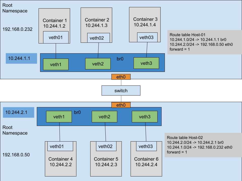
In this scenario we can see that 2 machines connected by a switch have the same setup. To be able to access an application in container 3 from container 6 we need:
- a default route( 10.244.2.0/24 via 10.244.2.1 ) to exit the namespace
- forwarding enabled between the bridge interface and physical interface
- next hop route for the network
- the same for the other host
# default routes
sabin@host-02:~$ sudo ip netns exec test2 ip route add default via 10.244.2.1

sabin@host-02:~$ sudo ip netns exec test ip route add default via 10.244.2.1

# forwarding enabled
sabin@host-02:~$ sudo iptables -A FORWARD -i br0 -o eth0 -j ACCEPT

sabin@host-02:~$ sudo iptables -A FORWARD -i eth0 -o br0 -j ACCEPT

# next hop for the 10.244.1.0/24 network
sabin@host-02:~$ sudo ip route add 10.244.1.0/24 via 192.168.0.232

# the reverse for host-01
# default routes
sabin@host-01:~$ sudo ip netns exec test2 ip route add default via 10.244.1.1

sabin@host-01:~$ sudo ip netns exec test ip route add default via 10.244.1.1

# forwarding enabled
sabin@host-01:~$ sudo iptables -A FORWARD -i br0 -o eth0 -j ACCEPT

sabin@host-01:~$ sudo iptables -A FORWARD -i eth0 -o br0 -j ACCEPT

# next hop for the 10.244.2.0/24 network
sabin@host-01:~$ sudo ip route add 10.244.2.0/24 via 192.168.0.50
Communication between containers on different hosts and different networks
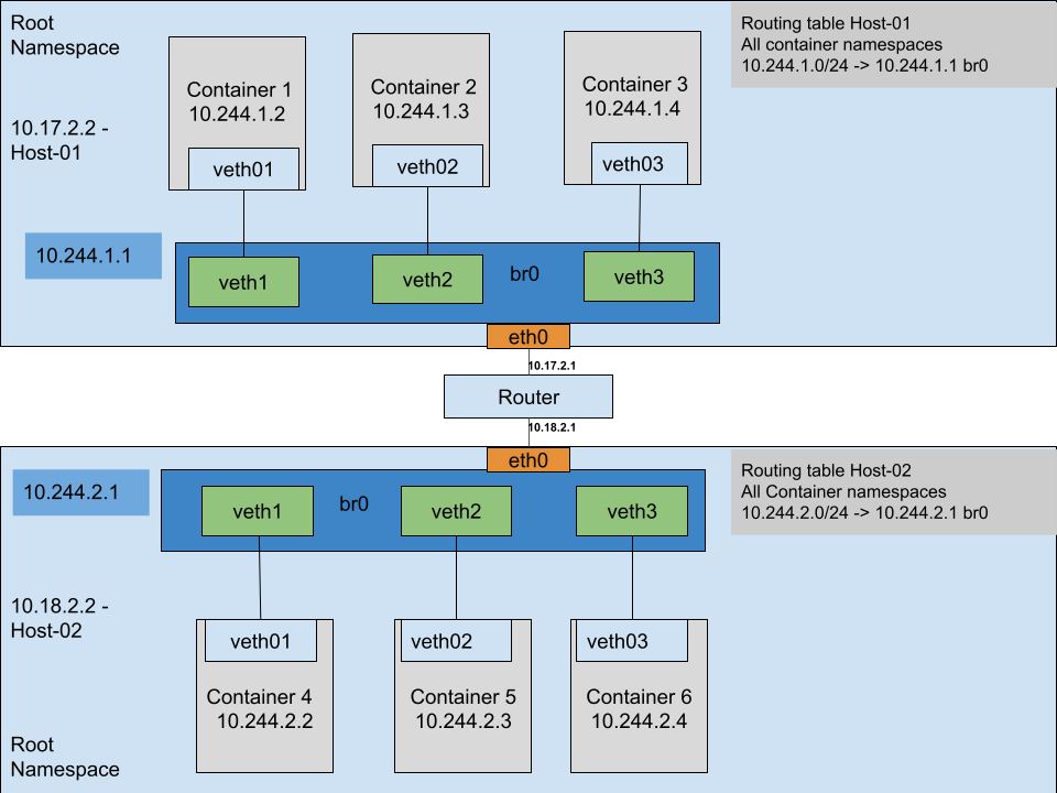
In this scenario let us analyze what happens when 2 containers communicate across networks. The above diagram shows 2 hosts in 2 different networks that are connected through a router.
The communication starts when container 3 sends a packet to container 6:
- container 3 analyzes its routing table( in its namespace ) and sees that the default route for all networks is 10.244.1.1( which is the bridge interface br0 )
- it sends the IP packet with SRC_IP=10.244.1.4 and DST_IP=10.244.2.4
- the kernel looks for a connected network 10.244.2.0/24 or other possible routes
- it finds that there is a default route on eth0 via 10.17.2.1( forwarding is enabled )
- it sends the IP packet unchanged to the router
- the router replies with a ICMP destination unreachable because it cannot find a valid route
The key takeaway from this scenario is that the routers on the way need to know where each private network is. This can seem easy on a simple architecture, but it complicates in more complex scenarios. Also it would be difficult to integrate with all router vendors and synchronize the state of the cluster.
One may think that maybe NAT will solve the issue. Let’s analyze the shortcomings of this by referring back to the container 3 to container 6 communication:
- assume the following set up on the root namespace of Host-01:
- -A PREROUTING -d 10.244.2.0/24 -j DNAT –to-destination 10.18.2.2
- -A POSTROUTING -s 10.244.1.0/24 -j MASQUERADE
- when the router receives the packet it can easily decide where to send it without an extra configuration
- when it reaches eth0 interface a mapping( PAT ) for the application needs to exist
- -A PREROUTING -d 10.18.2.2/32 -p tcp -m tcp –dport 25 -j DNAT –to-destination 10.244.2.4
- this means that multiple applications on the same port cannot coexist
- need to reach 10.244.2.4:25 through 10.18.2.2:25
- need to reach 10.244.2.3:25 through 10.18.2.2:25, need to change to 10.18.2.2:2525
- the application replies with an IP packet with the destination the public IP received as source( 10.17.2.1 )
You can see that this approach implies a tight coupling between containers configurations that needs a more complex setup.
A better solution would be to tunnel the traffic like a VPN solution, by wrapping the network packets in another layer that is unpacked at the destination. In this way, when the packets arrive at destination, the encapsulating layer is discarded and the resulting packets are processed as if the containers were on the same bridge.
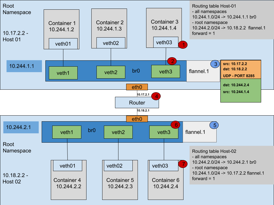
There are several options when choosing the tunneling technology for this packaging. Kubernetes project developed a plugin interface that facilitates development and integration of other plugins , each of them offering various features. For our example I used Flannel which is a layer 3 plugin. The project can be used without K8s, but you need to manage the network configuration store yourself.
Returning to the last diagram I will follow the entire scenario:
- step 1 – container 3 sends an IP packet to container 6 with SRC_IP=10.244.1.4 and DST_IP=10.244.2.4
- step 2 – packet is sent to 10.244.1.1
- step 3 – packet is received by the flanneld daemon that is connected to the flannel.1 interface
- packet is wrapped inside another packet with destination DST_IP=10.18.2.2 and SRC_IP=10.17.2.2
- the newly formed packet is sent through UDP to 10.18.2.2 host
- step 5 – the packet is received by the flanneld daemon on the other side and unwraps the packet
- step 6 – the initial packet is put on the bridge
- step 7 – the packet is processed at destination
Key takeaways for the last approach:
- routers on the packet’s path do not need an extra configuration
- no NAT is needed
- it satisfies the same network scenario
